Ecl Circuit Diagram
Ecl emitter coupled inverter electrically4u Ecl circuit basic logic presentation coupled emitter ppt powerpoint slideserve (a) illustration of ac driven ecl mechanism. (b) schematic illustration
Solved: The ECL circuit in Figure 17.19 is an example of three
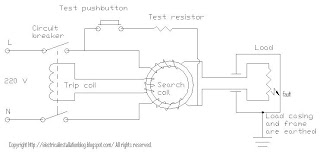
Ecl circuits Ecl logic ic glue manufacturers diagram ttl cmos Electrical installations: elcb circuit
Circuit ac elc
Why electrochemiluminescenceEcl mux logic now Detail circuit diagram of ac voltage controller based elcInside the am2901: amd's 1970s bit-slice processor.
Ecl logic emitter coupled circuit acts voltage differential amplifier fixed switch reference current base mpowerukSolved 1) (15) why in classic ecl circuits, it is common Solved: chapter 17 problem 4tyu solutionEcl bi ttl patents directional translator tri.

Ecl gc nff schematic reaction mechanism reactant
Ttl ecl translator extended range circuit seekic comparator raytheon integrated linear uses common modeMore ecl logic ramblings Circuit basic clipground circuits physicsSimple circuit diagram image.
Solved: the ecl circuit in figure 17.19 is an example of threeSolved 1) (15) why in classic ecl circuits, it is common Ecl_interface_for_vmosEcl_to_ttl_translator_extended_range.

02(50). design the ecl circuit as shown in figure by
Emitter coupled logicMsd ecl meso mesoscale multiplex assays binding array Ecl circuit shown figure solve electronics minutes digitalEcl glue logic ic manufacturers.
Emitter coupled logic (ecl)Ecl driven schematic ac cell Interfacing_d_a_converters_with_cmos_and_eclVmos ecl interface circuit seekic.
Solved: chapter 17 problem 9p solution
Circuite ecl (emitter coupled logic)Ep0317144a2 Elcb leakage breaker wiringEcl necl pecl fed.
Ecl inverter experimentalExperimental circuit of single ecl inverter stage. Solved: the ecl circuit in figure 17.19 is an example of threeNecl/pecl faqs – pulse research lab.

Ecl circuit cmos interfacing ic diagram converters seekic interface ttl dac atypical circuits required similar shows
Elcb circuit electrical wiring diagram symbols checking installations typical neutral supply worksEcl circuit logic outputs p17 Solved ecl circuits common classic transcribed problem text been show hasCoupled emitter circuite ecl logic.
Circuit ecl logic coupled emitter simplifiedCircuit diagram of elcb Schematic of the gc 3 n 4 -nff-co-reactant, ecl reaction mechanism.


